|
SND1
500mW Data Link Mesh Radio
-- Supports up to 735kbps
wireless link rate
-- Supports Point-to-Point, Point-to-Multipoint,
Multipoint-to-Point and Mesh topologies
-- Supports maximum 1024 nodes mesh network
-- High sensitivity: -114dBm@125kHz
-- Supports frequency hopping(FHSS)
-- Movement Speed: supports no less than 1250km/h
-- Wide temperature specification (-40°C to +85°C)
SND1 self-organizing network(Mesh) data link radio realizes the
centerless long-distance communication between large-scale nodes,
all nodes can communicate with each other independently without
interfering, supports large-scale dense node access to wireless
transmission, dynamic networking and flexible reorganization,
supports full-multiplexing communication, the node sends data at the
same time it can also receive the data of all other nodes without
interfering with each other, and in the absence of the center, it
can realize the interoperability of any node and all other nodes in
the network. Without interfering with each other, it can realize the
interconnection between any node in the network and all other nodes
in the case of no center.
SND1 data link mesh radio supports large-scale node access,
multi-hop self-organizing network, 500mW transmit power, -114dBm
sensitivity, maximum 735kbps effective data transmission rate, 2ms
ultra-low latency, which can be used for swarming drones, Internet
of Things, data chain, remote control, data collection, artificial
intelligence, military equipment and other application scenarios.
SND1 data link mesh radio has a variety of models to choose, the
appearance and functional characteristics of each model is the same,
only the working frequency band and networking scale is different.
SND1 500mW data link mesh
radio models
| Model |
Network scale |
Frequency bands |
| SND1-H460-500mW |
Max. 1024 nodes, up
to 16 hops |
453~470MHz |
| SND1-H495-500mW |
490~500MHz |
| SND1-H800-500mW |
820~854MHz |
| SND1-H900-500mW |
900~940MHz |
| SND1-F460-500mW |
Max. 256 nodes, up to
3 hops |
453~470MHz |
| SND1-F495-500mW |
490~500MHz |
| SND1-F800-500mW |
820~854MHz |
| SND1-F900-500mW |
900~940MHz |
Features:
- Frequency: different models support different
frequency bands, see models table
- Bandwidth: 1MHz/500kHz/250kHz/125kHz selectable
- Number of nodes and hops: Maximum 1024 nodes up
to 16 hops or 256 nodes up to 3 hops, see models table
- Frequency hopping speed: More than 1800 times per
second@1MHz, More than 900 times per second@500kHz, More than
450 times per second@250kHz, More than 225 times per
second@125kHz
- Effective data rate: Maximum 735kbps@1MHz,
370kbps@500kHz, 185kbps@250kHz,
92kbps@125kHz
- Full-multiplexing communication: support
- Air-to-ground LOS(light of sight) distance: more
than 30km
- Centerless self-organized network: support
centerless self-organized network, any node of the network is
destroyed without affecting the communication
- Network construction time: within 1 second
- Wireless transmission delay: minimum 2ms
- Dynamic topology: support dynamic topology,
support node joining and leaving, network topology change and
deformation can be normal communication
- RF power: 500mW(27dBm)
- Sensitivity: -114dBm@125kHz, -111dBm@250kHz,
-108dBm@500kHz, -105dBm@1MHz
- Frequency stability: ≤1ppm
- QPSK modulation LDPC coding
- Encryption: 128-bit encryption
- Movement Speed: supports no less than 1250km/h
- Low power consumption: less than 1W when
receiving, less than 4W when transmitting, average working power
consumption less than 2.5W
- Operating voltage: 7V~36V
- Operating temperature: -40~+85°C
- Dimensions: 50*50*17.3mm
- Weight: 56g
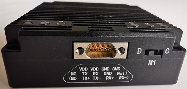
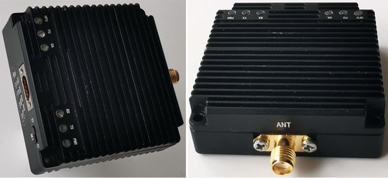
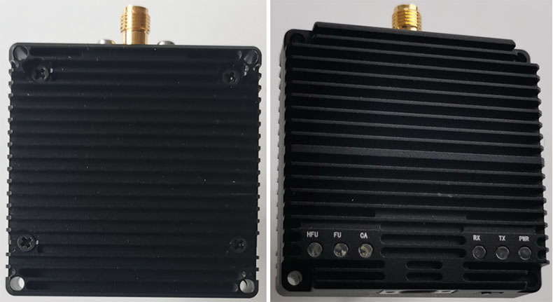
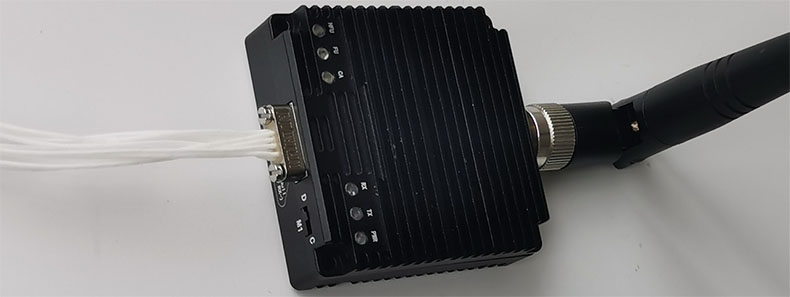
I/O
| I/O |
Description |
| J30JZ-9PIN connector |
Power-input, uart, M0 control signals |
| M1 Dipswitch |
M1 control signal |
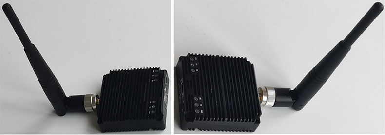
| SMA female |
Antenna port, the required antenna impedance
is 50Ω |
| PWR LED |
Power led, Red light on normal powered. |
| TX LED |
Green, data transmission led, briefly light
during power on self-test, light when data is transmitting. |
| RX LED |
Green, data receiving led, briefly light
during power on self-test, light when receiving data. |
| CA LED |
Blue, interference led, briefly light during
power on self-test, light in configuration mode. In
transparent transmission mode: When it light on, it means
exist interference and the brighter the light, the stronger
the interference signal. |
| FU LED |
Blue,data cache indicator led, briefly light
during power on self-test, light when data cache is full. |
| HFU LED |
Blue,data cache indicator led, briefly light
during power on self-test, light when data cache is half
full. |
Uart port
Before shipment, the uart port can be assembled as TTL uart port, or
RS232 uart port, or RS422 uart port according to customer’s
requirement. The TTL/RS232 uart port data bit is 8-bit, the stop bit
is 1-bit, and there is no parity check bit. When the radio operates
in configuration mode, the baud rate is fixed at 9600. When
operating in data transparent mode, the baud rate can be configured
as 9600 / 19200 / 38400 / 57600 / 115200 / 230400 / 460800 / 921600.
Suggest selecting a baud rate of 921600 when the RF bandwidth is
1MHz; When the RF bandwidth is 500kHz, select a baud rate of 460800;
When the RF bandwidth is 250kHz, select a baud rate of 230400; When
the RF bandwidth is 125kHz, select 115200 baud rate, so that the
uart port baud rate matches the wireless throughput to avoid packet
loss during uart port data transmission and reception. uart ports
are mainly used for radio parameter configuration and data
transmission.
M1 Dipswitch
M1 and M0 (M0 PIN of J30JZ-9PIN connector) signal is used for
control the radio operating mode.
The radio supports two operating mode: data transparent transmission
mode and configuration mode. Users can configure the M0 level and
the M1 status to put the system in the corresponding mode. When the
voltage levels of M0 and M1 are not consistent, the system operates
in configuration mode; When the voltage levels of M0 and M1 are the
same, the system operates in transparent mode. The M0 and M1 pin
systems have been pulled up to a high level internally and are in
transparent mode. When M0 is suspended, the M1 dip switch is turned
to the “C” side, and the system enters configuration mode. The M1
dip switch is turned to the “D” side, and the system enters
transparent transmission mode. The configuration mode and
transparent transmission mode are switched in real-time without
restarting the system.
When the radio is in configuration mode, it only responds to
configuration commands and does not transmit received serial data to
the wireless port. It also does not output data to the serial port
when receiving signals from the wireless port. In configuration
mode, the uart port baud rate is fixed at 9600, with 8 data bits, 1
stop bit, and no parity check bits.
When the radio is in transparent transmission mode, if the received
serial data is a configuration packet, the radio will perform
parameter configuration; If the received serial data is not a
configuration packet, it will be transmitted to the wireless port,
and the signal received from the wireless port will be forward to
the serial port.
In configuration mode, only local configuration parameters are
supported, while in transparent transmission mode, both local and
remote parameter configurations are supported.
 SND1 500mW Data Link
Mesh Radio
SND1 500mW Data Link
Mesh Radio
|